![]()
How To Install A Magnetic Lock On A Storefront Door
Introduction
A magnetic lock is an electronic device that mounts overhead on a commercial door. It uses electromagnetism to hold the door in the closed or locked position. Sometimes referred to as maglocks, these electronic locks are one of the most preferred ways to achieve a keyless lock system for a storefront door. In this article we will explain in detail how to install a keyless entry magnetic lock system on any storefront door.
Components Of A Magnetic Lock
As you can guess a magnetic lock is a type of door lock that uses magnets. To further understand what and how a magnetic lock works let's explore the anatomy of a magnetic lock. A magnetic lock consists of the magnet itself, which is typically mounted to the top of the door frame, an armature (the component that the magnet attaches to), and brackets which allow the magnet to mount to the door frame.
![]()
Considerations Of A Magnetic Lock System
Price
Most building owners are adamant on getting the lowest price for any kind of construction need for their building. But, when it comes to a magnetic lock system, you do not want to nickel and dime the security of your building. What most building owners find is that you get what you pay for. Many magnetic lock kits are flooding big box online retailers and often catch people's attention due to the low price. However, the "to good to be true" pricing of these magnetic locks is often reflected in the quality and certification. These magnetic locks are typically manufactured overseas, making any kind of technical support next to impossible. But what is most concerning is these products are not UL certified, meaning they should not be used on commercial buildings to begin with. We recommend using a security product manufactured by a reputable company like American Entrance Controls.
Ease Of Installation
Magnetic lock systems can be very complicated if a wiring diagram is not provided. When purchasing a magnetic lock kit be sure a step by step wiring diagram is included. Most magnetic lock kits on the market today do not include a step by step wiring diagram, making installation a "guess and check" process. In fact, about 75% of magnetic lock kits purchased results in the building owner or customer contacting a professional locksmith or electrician to install the product for them, since no wiring diagram was included. We recommend purchasing a magnetic lock kit from American Entrance Controls, as each kit comes with a step by step wiring diagram making installation as easy as following the wiring pin out.
Lock System Function
Much of the functionality of a magnetic lock system ties to the price of the kit. After all, the more bells and whistles you require, the higher the cost the kit will be. For this installation example, we will go over how to install the American Entrance Controls Keyless Entry System with a keyswitch override. This particular magnetic lock system includes a magnetic lock, request to exit button, power supply, pin code entry keypad, and an override keyswitch. This lock system is great for any business that requires after hours door access to employees only. Here's an example of how this lock system works. During business hours the door is unlocked, and pedestrians can freely enter or exit the building. This is done through the keyswitch. The building owner can simply turn the keyswitch to disable the lock system, keeping the magnetic locks "unlocked". During after hours, the manager can use the key to enable the lock system, so the magnetic locks are "locked." Employees entering the building will have to use the keypad and enter the correct pin code in order to unlock the door. Employees in the building can freely exit the building by pressing the request to exit push button to unlock the door so they can exit.
Installing Your Magnetic Lock System
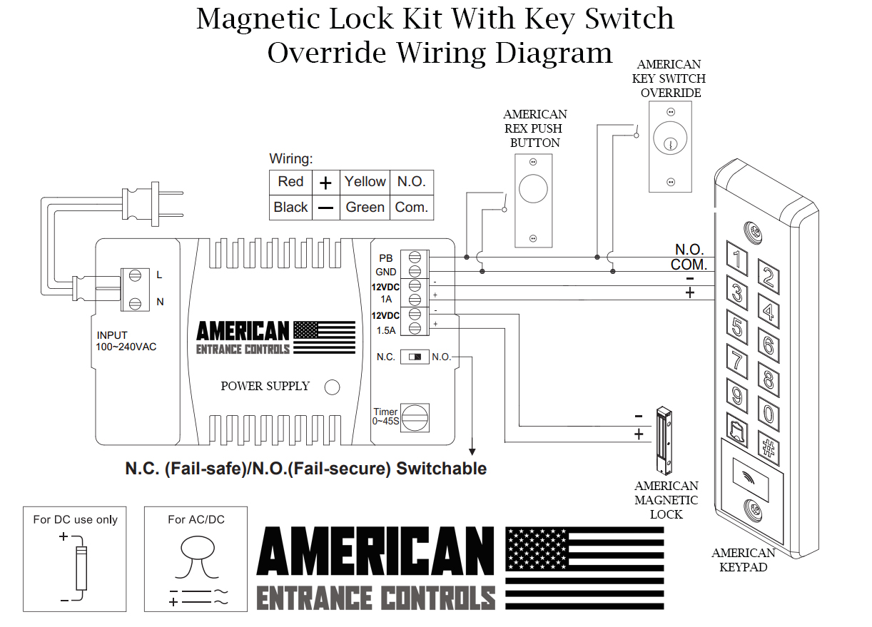
For the sake of this installation guide we will go over the most common storefront door magnetic lock set up. We will explain how to install a American Entrance Controls magnetic lock kit with a key switch override switch. Below is an illustration of the American EntranceControls magnetic lock kit.
![]()
Step 1: Mounting The Power Supply
The first step we recommend is mounting the power supply. The American Entrance Controls power supply can be plugged directly into a standard 110V power outlet. Many customers prefer to mount the power supply above the door, or in the ceiling. It is really up to the building owner, but keep in mind signal and power wires will be routed from the power supply to each of the locking accessories so the power supply should be mounted relatively close to the accessories. Another point to remember is mounting the power supply to far away such as 10 bedrooms down, could result in a voltage drop in the wires ran to the locking accessories. In access control voltage drops can occur in the wire runs if the source power is too far away from the locking devices they are energized. In most applications the power supply is mounted right above the door, so wire runs and voltage drop calculations are not needed.
Step 2: Route Power Wires and Signal Wires To Proper Location
Keep the power supply unplugged from the wall outlet, so it is not powered. Next, wires will need to be ran from the power and signal output terminals on the American Entrance Controls Power Supply. It is important to use the proper gauge wires when installing any security door control products. Using too small of a gauge of wire can result in a voltage drop in the keypad, maglock, or other access control device. For access control we recommend 18 gauge stranded, 4 conductor wire. When routing wires from the American Entrance Controls power supply we recommend using tape to wrap around the wires and label with a marker. This will save you time from having to follow and trace each wire later on. The installer can simply read the tape on the wire and know exactly which power supply output it represents. For this installation example we will assume you are using 4 conductor wire with the colors: RED, BLACK, YELLOW, GREEN.
![]()
Wire Cable 1 (4 conductor):
Connect the red wire to 1A on the American Entrance Controls Power Supply and label the wire as "Keypad +". Then connect the black wire to 12VDC on the power supply and label "Keypad -." Use the yellow wire to connect to "PB" on the power supply and label "KEYPAD N/O". Use the green wire to connect to "GND" on the power supply and label "KEYPAD COM".
Wire Cable 2 (4 conductor):
Use the yellow wire to connect to "PB" on the power supply and label "KEYSWITCH N/O". Use the green wire to connect to "GND" on the power supply and label "KEYSWITCH COM". The red and black conductors are not used.
Wire Cable 3 (4 conductor):
Use the yellow wire to connect to "PB" on the power supply and label "REX N/O". Use the green wire to connect to "GND" on the power supply and label "REX COM". The red and black conductors are not used.
Wire Cable 4 (4 conductor):
Connect the red wire to 1.5A on the American Entrance Controls Power Supply and label as "MAGLOCK +". Then connect the black wire to the lower 12VDC on the power supply and label "MAGLOCK -." The other 2 conductor wires, green and white, can be cut short and disregarded as they will not be used.
Step 3: Mount Accessories In Proper Locations
Next, we recommend mounting all of the accessories: maglock, keyswitch override, request to exit push button, and keypad. We recommend mounting the keypad on the exterior side of the storefront door frame right beside the pull handle. This way pedestrians can identify the keypad right away. For the request to exit button, we recommend installing that on the interior side of the door frame, right beside the push bar. Again, this is so pedestrians can quickly identify the button to request to exit. The key switch override should be mounted higher on the door frame. This key switch can be mounted in a more hidden location, as it will only be accessible to the building owner, manager, or security guard for enabling or disabling the electric lock system.
Step 4: Route Wires To Accessories
All accessories that are mounted directly to the storefront door frame can have wires ran to them concealed within the storefront door frame. Storefront door frames are hollow extrusions, so wires can easily be concealed within them. Simply drill a hole in the storefront aluminum and snake the wire through the hole. If it is too difficult to route wires in a concealed manner a flexible aluminum conduit can be used to safely conceal the wires. The aluminum conduit can be mounted on the door frame.
![]()
Step 5: Connect Accessories To Power Supply
Connect Keypad
Connect the "Keypad +" to the + wire on the keypad. Connect "Keypad -" to the - wire on the keypad. Connect the "KEYPAD N/O" to the N.O. wire on the keypad. Connect the "KEYPAD COM" to the COM wire on the keypad.
Connect Request To Exit Push Button
Connect the "KEYSWITCH N/O" to one of the wires on the Key switch Override. Connect the "KEYSWITCH COM" to the other wire on the Key switch Override.
Connect Request To Exit Push Button
Connect the "REX N/O" to the N.O. wire on the Request To Exit Push Button. Connect the "REX COM" to the COM wire on the Request To Exit Push Button.
Connect Maglock
Connect the "MAGLOCK +" to the + wire on the maglock. Connect "MAGLOCK -" to the - wire on the maglock.
Step 6: Power Lock System On and Test
Double check all wiring. Plug in power supply to 110VAC power outlet to power the system on. Verify the keyswitch override is turned off, so that the magnetic lock is on. Turn the keyswitch override switch to on, to verify the maglock is unlocked. Using the installation guide for the keypad, program the keypad to the appropriate pin code for entry access. The American Entrance Controls keypad is designed to accept security cards as well. Test and verify that the REX push button functions properly. Pressing the REX push button should unlock the maglock. On the power supply is a timer potentiometer, which adjusts the hold time for the activation signal. We recommend this adjustment is set to atleast 10 seconds. This way once a pedestrian enters the pin code, he will have 10 seconds that the maglock will be unlocked and he or she can enter the building. Likewise, with the request to exit push button, once pressed, the pedestrian will have 10 seconds to exit the door while the maglock is unlocked. The hold time is adjustable for up to 45 seconds and is dependent on the installer's needs or requirements.
Conclusion
Magnetic locks can provide security to a storefront entrance door. If you are in need of a magnetic lock door system or keyless entry system for your commercial door we recommend American Entrance Controls products. Each American Entrance Controls magnetic lock kit includes a wiring diagram of how to wire each door control accessory. With American Entrance Controls you don't have to worry about not knowing how to connect certain access controls products within your lock system. Shop today and receive FAST and FREE shipping.
![]()
![]()
DISCLAIMER:INFORMATION PROVIDED THROUGH THIS SITE IS PROVIDED TO YOU AS IS WITHOUT ANY EXPRESS REPRESENTATIONS OR WARRANTIES OF ANY KIND, AND WE MAKE NO REPRESENTATION OR WARRANTY THAT THIS SITE (OR ANY INFORMATION PROVIDED IN RESPONSE TO YOUR INQUIRY), WILL BE ACCURATE, COMPLETE, OR ERROR-FREE.YOU AGREE THAT YOU MUST EVALUATE ALL INFORMATION AND RESPONSES, AND THAT YOU BEAR ALL RISKS ASSOCIATED WITH, THE USE OF THIS SITE, INCLUDING ANY RELIANCE ON THE ACCURACY,COMPLETENESS, OR USEFULNESS OF ANY INFORMATION OR MATERIALS MADE AVAILABLE THROUGH THIS SITE.